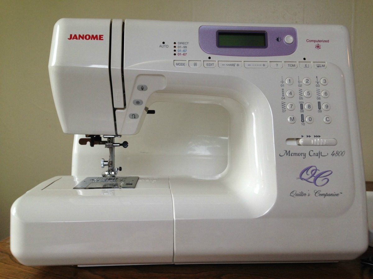
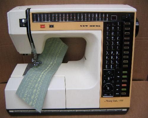
Janome Memory Craft 6000 Service Manual
• SERVICING MANUAL. • TABLE OF CONTENTS To change the face plate and top cover.
3 To change the belt cover unit..4 To change the bed cover unit..5 To change the base unit..6 To adjust the needle position..7 To adjust the needle bar height.. • TO CHANGE THE FACE PLATE UNIT AND TOP COVER UNIT FACE PLATE UNIT TO REMOVE Remove the two screws, and remove the face plate. TO ATTACH Tighten the two screws slightly, and attach the face plate.
Close the face plate, and check the unevenness between The face plate and arm. Tighten the screws securely. • TO CHANGE THE BELT COVER UNIT TO REMOVE Loosen the screw A and remove screws B, C and the washer. Loosen the screw D completely, and remove the belt cover unit. TO ATTACH Insert the belt cover in the front panel. Replace screws A, B.
- Examples: “SL-M2020W/XAA” • Include keywords along with product name. Drajvera dlya klaviaturi hp kb 0316 10. Examples: 'LaserJet Pro P1102 paper jam', 'EliteBook 840 G3 bios update' Need help finding your product name or product number? This product detection tool installs software on your Microsoft Windows device that allows HP to detect and gather data about your HP and Compaq products to provide quick access to support information and solutions. Technical data is gathered for the products supported by this tool and is used to identify products, provide relevant solutions and automatically update this tool, to improve our products, solutions, services, and your experience as our customer. - Examples: LG534UA • For Samsung Print products, enter the M/C or Model Code found on the product label.
Janome Memory Craft 9000 Service Manual. Related Manuals for Janome Memory Craft 9000. Sewing Machine Janome MEMORY CRAFT 9500 Instruction Book. Janome sewing. Click to enlarge. New Home Memory 7 Service Manual, wpe151.gif (20610 bytes). Anno 2070 key generator. New Home 6000 MC Service Manual, wpe1AF.gif (75106 bytes).
• TO CHANGE THE BED COVER UNIT TO REMOVE Remove the base cover (see page 6). Remove the two screws A, and remove the base lid. Remove the two screws B, and remove the bed cover unit. Then pull out the connectors from the connector supporter and disconnect them.
• TO CHANGE THE BASE UNIT TO REMOVE Remove the base cover. Pull the connectors for the X-axis and Y-axis motors from “A” board.
Remove the 4 screws and the base unit. TO ATTACH Follow the above procedure in reverse. Check the position of feed dog “UP and DOWN”. NOTE: 1) Set The base unit that the right side of knee lifter link (4) claw should match the knee lifter plate on the base unit (see page 30).

• TO ADJUST THE NEEDLE POSITION When straight stitch #2 is selected, the needle should be at the center hole of the needle plate. When the zigzag stitch is selected with the zigzag width set to the maximum (7.0), the clearance between the side of the needle and the outer edges of the left and right needle plate holes should be 0.2 mm or more. • TO ADJUST THE NEEDLE BAR HEIGHT The needle bar height means the distance between the upper edge of the point of hook and the upper edge of the needle eye when the point of the hook meets the right side of the needle in the upward travel of the needle bar from the lowest position with stitch pattern #2 ( selected. • TO ADJUST THE HOOK TIMING When pattern #2 ( ) is selected, the amount of ascending travel of the needle bar from its lowest position to the position where the tip of the rotary hook exactly meets the right side of the needle should be 3.25 to 3.55 mm.
• TO ADJUST THE UPPER SHAFT SHIELD PLATE POSITION NOTE: When the machine is set for zigzag stitching, the needle should start to swing 7.0 to 8.2 mm above the surface of the needle plate. Remove the top cover unit. Turn on the power switch. Then select zigzag pattern #8 (see page 8). Turn the hand wheel toward you slowly with your hand until the needle starts to swing. • TO ADJUST THE NEEDLE THREAD TENSION Turn on the power switch, select the pattern #9 ( ) and press the S/S key to turn the hand wheel 2 to 3 rotations. Open the face plate and adjust the thread tension with a screwdriver in the direction of: A to looser the tension.
